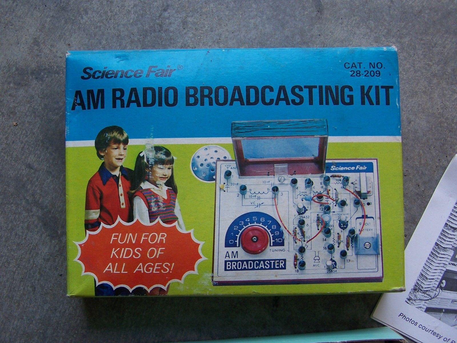
Today (October 31) in 1977 marks a starting milestone in my personal career. It was the day I stopped going out for Trick-or-Treat and got started in the world of hobby electronics. I had some money left over from a birthday gift not long before and was at the mall, hanging around the Radio Shack store, when I noticed this interesting electronics  project for under $10. It was an AM Radio Broadcasting Kit. I knew very little about electronics theory at the time, but was always interested in electronic items. It seemed a natural progression for a hobby. Besides, the opportunity to be able to broadcast whatever I want to say “up to 40 feet away” for only $7.95 + tax was too great to pass up. So I bought the kit, and since then, I was hooked on the hobby!
While every other kid in the neighborhood was getting ready to go door to door for treats, I was getting ready to build a radio transmitter. I had the parts spread all over the dining room table and the instruction manual at the starting page. In other words, I did not review the entire assembly instructions BEFORE getting started on this kit, as it would have made sense to do that first. But I was just an impetuous and anxious kid.
The kit itself was relatively simple compared to other electronics kits sold at Radio Shack. There is basically a couple of transistors, a handful of basic parts like resistors, capacitors, etc., and specialty components like an audio transformer, tuning capacitor, and hand wound antenna loop. The latter was the most difficult part of the kit because it took so much time to build. Basically, you had a 3″x4″ plastic frame that was 1/2″ deep. You needed to start winding a bunch of 30-gauge (very thin) enameled wire around the outside of the frame, placing each successive loop of wire next to the previous loop. After you span the 1/2″ width, you start winding another set of loops over the first set. I think it was a total of two sets of loops. It took a lot of time for my “kid hands” to complete this, but they at least made the first set easy enough to wind by using double sided tape on the corners to keep each loop of wire in place as you wind it.
The main part of the kit is the base, which is made of white plastic having a silk-screened schematic on it. Many tiny holes are drilled in the base to put the parts leads through. This keeps the parts in place and helps to visualize the schematic to those who are new at electronic schematic concepts (like I was at the time).
 The means used to interconnect the parts electrically was not through the use of a hot soldering iron, but through innovative spring coil clips. These clips were inserted through a series of larger holes in the base. When you inserted a part, you would connect its leads underneath by sliding it between the metal coils sticking out through the bottom of the base. Multiple parts could be connected to any coil clip, thus creating the connections.
It took me about two hours to finish the assembly, including winding the antenna, and I was quite anxious to try it out. So, I took the completed kit over to the kitchen counter where the household radio was sitting and proceeded to transmit my voice. The first thing I did was tune the kit’s control to the middle of the scale. There were no official AM frequency markings on the kit. I only had to assume the labeled range of 0 to 10 represents the full AM frequency scale found on most radios.
After hooking up the 9-Volt battery, I started talking into the supplied “minimalistic” aluminum cased crystal microphone. At the same time, I started tuning the kitchen radio from one end of the scale to the other. About halfway down the scale, I heard the static diminish greatly. Tuning it just a little bit more allowed me to hear everything I was saying into the microphone… IT WORKED!!! Needless to say, I was happy to hear this. So right away, I took the kit to the dining room table and tried again… NOTHING… only static. Well, at least I learned at an early age about “truth in advertising.” Technically, it was the truth because it states “UP TO 40 feet away.”
 Over the next few days, I used references from electronics books in my school’s library to find out what might have gone wrong with the kit. After all, we had no Internet (or BBSs for that matter) to find solutions to the problem. What I learned was that AM is a very picky means of transmitting at low power, which is what the kit was. AM is also quite finicky, needing the conditions to be “just right” to work effectively. This includes removing obstacles that might be blocking the signal, along with orienting the antenna properly, otherwise, it’s signal distance would decrease drastically. I eventually mapped out places in the house where it would still transmit to the kitchen radio. There was no pattern to the various transmit locations, but good locations were quite spotty and scattered.
In the end, it was a good starter kit for getting into electronics at the time. For that matter, it might still be somewhat useful in that capacity today. The parts being used might be somewhat antiquated, but it would be possible to find or fabricate every part used for the circuit and recreate your own little WKRP radio station!
Thanks for the excellent memories. I thank my father who got me started in electronics with 65 In 1 kit back in 1975. I have this broadcaster kit STILL. I seem to misplaced my manual. Could you please scan the 4 or so pages for me and email it for my archives?
THanks for your time.
Unfortunately, that isn’t my original broadcast kit. Mine broke decades ago. I wrote the article after being reminded about the time I had one as I saw the same item during an eBay browsing session. The pics there proved useful for the article. I would like to get another identical AM Broadcaster someday, or to at least have the schematic to build the circuit from scratch.
Jeff,
I have two am broad casting kits with instructions. I had a ham radio operator try to fix them but it still dose not broadcaster. Could you look at for me
An excellent article on a kit where many young people where introduced to the world of radio and AM broadcasting. I, myself, discovered it with another offering from Radio Shack about a decade early.
The Radio Shack “Science Fair” line of P-Box kits offered several different kits which used terminals that would be pressed into the perforated holes in the plastic “chassis” to build the kit. I purchased and completed the AM Wireless Microphone kit but Radio Shack also offered an FM wireless microphone kit as well. Once I understood the basics of AM transmission I started to design and build my own AM transmitters with a little assistance from the ARRL handbook. It’s pretty obvious that these early low power kits broadcasted with such a limited range they were operating well below the guidelines of the FCC Part 15 regulations.
My website offers resources for those who want to dabble with Part 15 broadcasting for fun and education. Schools and hobby radio enthusiasts can still use this legal, license free method of low power radio broadcasting to have fun as well as to educate.
Thank you for your input!
One thing about the information your website can offer are resources for those who collect vintage AM radios, like the cathedral and tombstone radios of the 1930’s and 1940’s.
Being able to build and use legal, low power AM (or FM) transmitters will allow those owners to broadcast their own content, in home, to demonstrate those radios, as designed, to their friends. In fact, I would like to do so myself someday. Archive.org has some nice royalty free vintage radio broadcasts that would work so well for such a setup.
Jeff, thank you for the great suggestion. I often get questions from antique radio collectors and having been one myself I can understand they can use resources for not only furthering their restoration efforts but also sources for suitable program material. I’ll be adding those resources shortly as well as a link to your wonderful blog.
I remember I once had a Radio Shack kit with an AM transmitter, the only thing I remember about it that it used the integrated circuit LB 8015, can anyone help me with more info about this one?
I had one of these and pretty decent range,well beyond the stated 40ft. Audio quality wasn’t to bad either. I wouldn’t mind getting hold of one of these again.
I heard that if you replace the antenna loop with a long wire, you got better performance as a transmitter… at the cost of the extra space the antenna takes up.
I have the same broad caster kit how ever its not transmitting. Do need a external antenna
Even with the loop antenna, you should be able to hear something when an AM radio is sitting right beside the transmitter.
Chances are, a circuit component is bad. You might want to turn the transmitter on, then tune an AM radio near it and listen for a “dead spot” in the static. If you hear one, turn the transmitter tuning knob a bit until the dead spot goes away, then retune the AM radio to hear the dead spot again. If that happens, your transmitter is at least working by sending a signal. If you can’t hear anything you say in the microphone, then something is probably wrong in one of the early stages of the transmitter, either with the pre-amp or mixer. If you don’t hear any dead spot on the AM radio when the transmitter is on, then it’s most likely a later stage of the circuit, probably the oscillator or RF amplifier.
I LOVED that kit. I boosted the power a bit by running it on 12 volts, tied the audio into my stereo and played JD for my sister. It actually sounded pretty good. I still remember parking that bad boy on 1400 kHz…more or less.
Today, among other things, I am a contract broadcast engineer. No matter what I work on, nothing is ever as much fun as that little Radio Shack transmitter kit was.
Boosting it from 9v to 12v probably worked well on that kit design. It would increase output power, but transistor biasing may have also been on an upswing from the extra voltage and could have caused signal clipping. However, since AM radio has low fidelity, any clipping may have gone unnoticed. The only other issue would be driving the electronic components above their tolerances, risking the chance a part could blow out.
Do you know where I can get replacement transmitter for this kit
The kit IS the transmitter. Is there a particular part of the kit you may be referring to instead?
I had a friend look at the kit and he said it was a transistor that was bad. Transistor would cost $50.00. Where I could find another kit or other broadcasting kits.
Paul
Do you have the number on the transistor? I find it very hard to believe that a replacement would cost $50. It might easily be fixed with a substitute transistor having similar electrical characteristics.
I have two broadcaster kits assemble however they don’t broad cast.Could you look at it