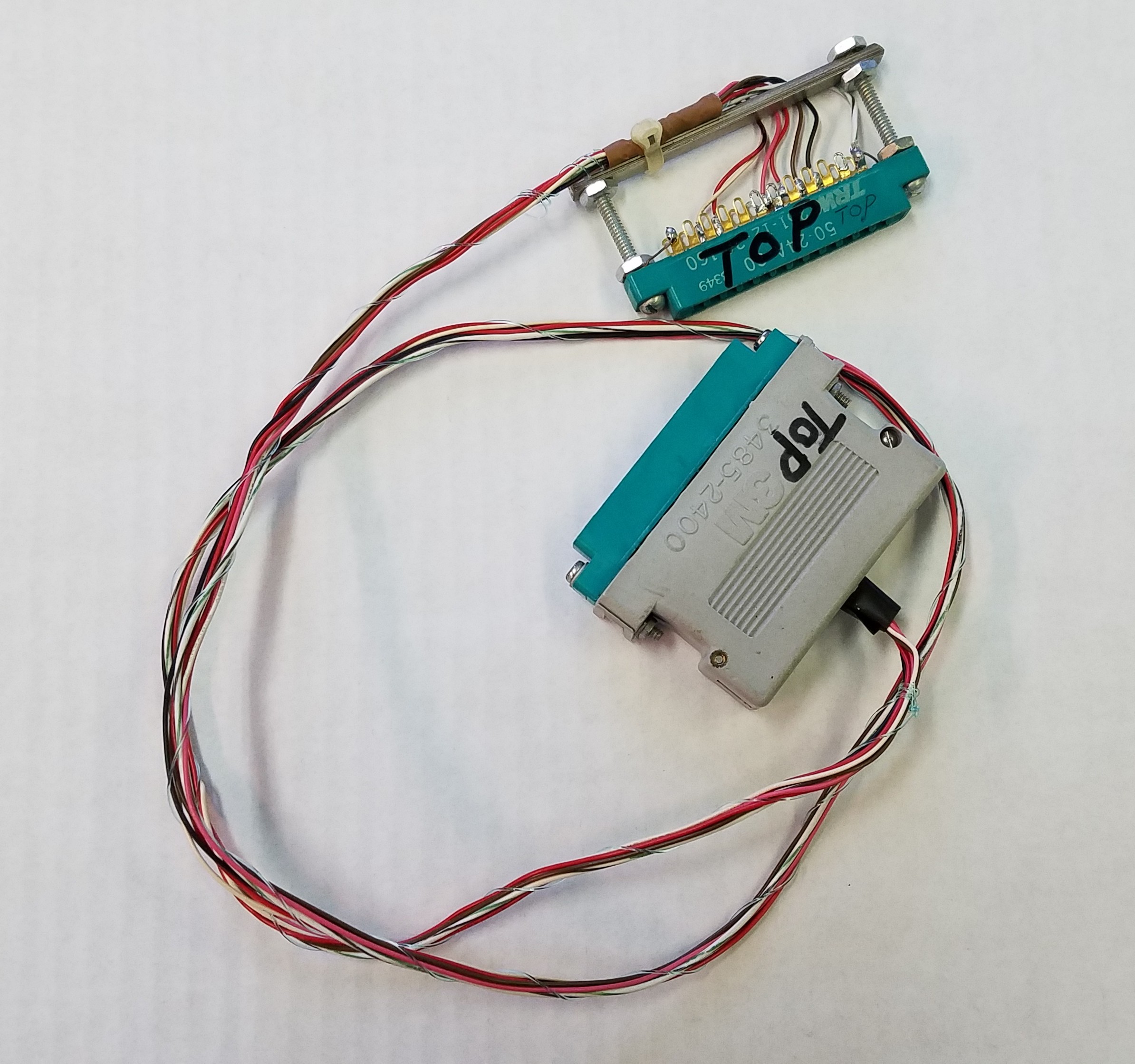
In a previous article, I introduced a hardware and software technique that allows for active data transfer from one Commodore 64 to another via a custom User Port cable connecting the two computers together. That article described how a modified version of the PAL assembler can invoke a direct compilation, not to disk or RAM, but through the User Port… directly into the RAM of another Commodore 64. This post will detail the software side of the process, describing techniques and source code that could be implemented in your own programming with some minor changes. This code could also be modified to work on any other Commodore (even non Commodore) computer having a 6522 CIA and running a 6502 compatible CPU.
Now for a little review of how this came to fruition…
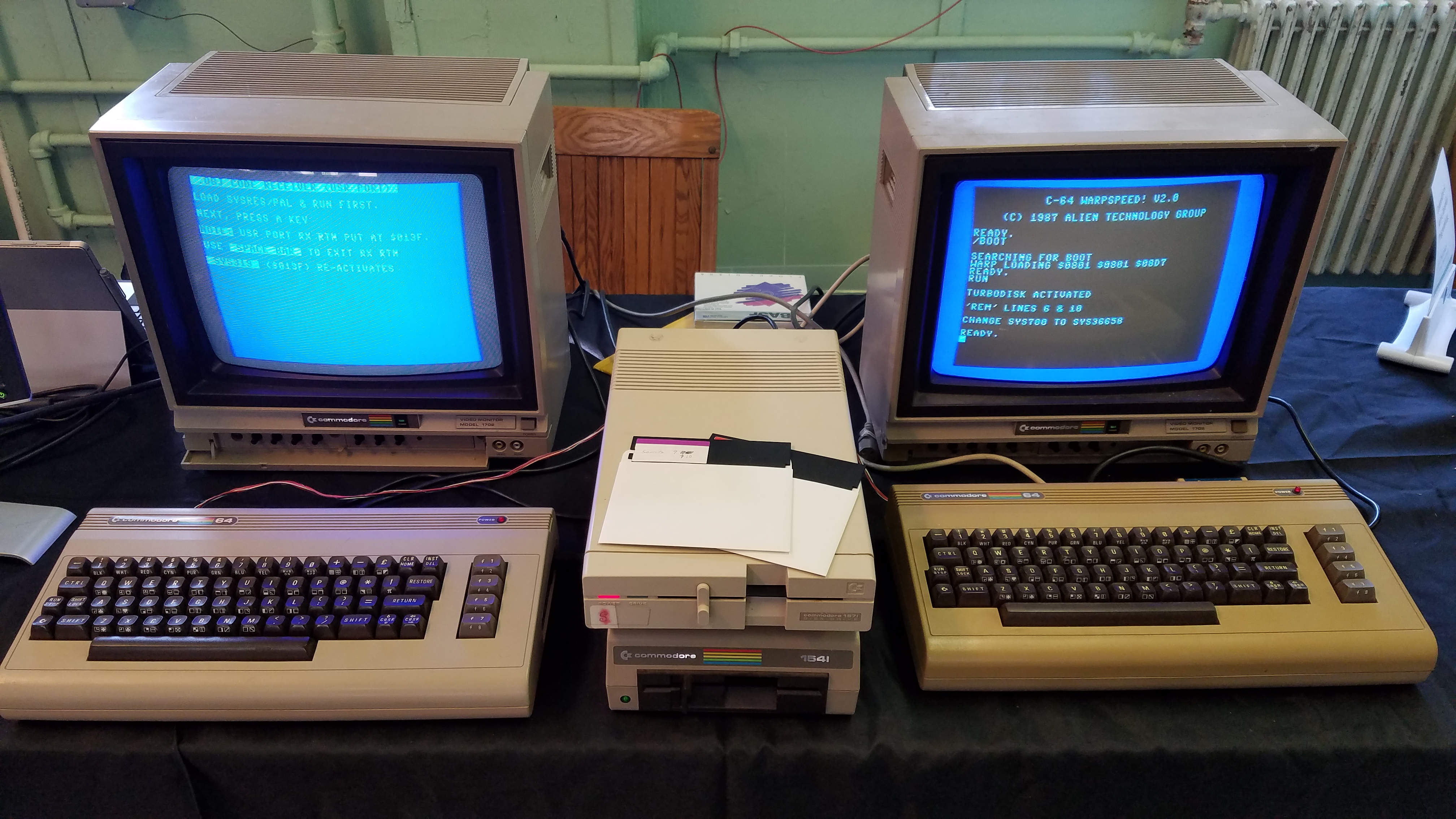
I am not the originator of this code. Years ago, a fellow HAM radio operator, named John, and myself were talking to each other over the air when the subject of vintage computing came up. He mentioned how he did a lot of Assembly programming on his Commodore 64 back in the 80s. In fact, he nearly worked exclusively in Assembler. His favorite compiler was the PAL compiler, due to it working directly from the BASIC environment. After our talk on the air, John sent me .D64 files of everything he had, which yielded a lot of his original source code. One of the most intriguing collections of software from him is his modified version of PAL that will compile a program to a subroutine he preloads in his development environment that intercepts the compilation process and sends the compiled object code directly to another Commodore 64 that’s connected to it via the User Port. The receiving Commodore 64 would be running a small routine that waits for and saves the received data during the compilation process. When finished, the newly compiled program can immediately be executed on the receiving Commodore 64. I demonstrated this process at the Vintage Computer Festival XII (YouTube link).
I had possession of this source code for quite some time, and only recently I found the time to pique my curiosity as to how he made this direct hardware transfer possible. After a period of combing through and decoding his source code, I found the code that’s used on the receiving computer to get and store the modified PAL compiler output. I have yet to find the code that modifies PAL to see how the data transmits, so I make a few speculations in the description below as to what I think is being done for handshaking and flow control between the two connected computers.
What I first discovered is that the actual machine code that does the dirty work on receive has already been precompiled and “embedded” in the source code that becomes the program that launches the receive process. In other words, the functional machine code is directly copied into the cassette buffer from a byte stream in the receive program’s compiled output, kind of like how DATA statements are used to POKE machine code into memory in a BASIC program. So I had to deal with a sequence of decimal numbers, and had to hand decompile values like “169, 01, 133, 251…” into LDA #$01, STA $FB, etc. before I could figure out the program code. Therefore, the code listed below is sort of a pseudo-code, which could easily be adapted to any Commodore 64 Assembly language compiler. The code is broken down into segments to better describe its functionality.
Here goes…
var1 = $FB           ; Contains low order address to store next received byte
var2 = $FC           ; Contains high order address to store next received byte
; Starting address above is start of BASIC program space, $0801
The code manages an incremental low/high address in Zero Page where data is to start being stored as it is being received. The variables var1 and var2 represent the Zero Page address containing the low/high address bytes. The Commodore 64 has four unused bytes at addresses $00FB, $00FC, $00FD, and $00FE, all but the latter which are utilized in this program. As you may know, using Zero Page addressing on a 6502 saves at least one clock cycle over non-Zero Page addressing. I suppose John tweaked this code for speed by doing so.
var3 = $FD           ; Unused Zero Page location for temp use
CIA2DDRB = $DD03     ; CIA 2 Data Direction Register Port B
CIA2DPB = $DD01      ; CIA 2 Data Port B
keyboardCode = $CB   ; Zero Page memory location to read keyboard matrix
The variable var3 is used to capture the byte being sent. Since the User Port is being used for data transfer, this theoretically offers a maximum of 8-bits that can be used to transfer data… IF… you want to waste time managing comparing of values in order to maintain handshaking. This is because any byte over an 8-bit connection could be interpreted as either a value needed to be transferred, or a control code. In order to facilitate handshaking while maximizing the bit width, 8-bit transfer in the code would have to watch for a unique sequence of bytes to know that data being sent is a control sequence instead of actual data. It would require n-passes for an n-count of a unique control byte sequence, along with tracking the bytes being sent until the entire control code is received and interpreted. Very inefficient.
Instead, the data being sent is split into 4-bit nibbles from the sending computer. Only two passes per byte being sent is needed. No guesses as to the data being a control code or actual data via an 8-bit transfer because by sending data in 4-bit nibbles, the remaining 4-bits can be used as handshaking flags between the transmitting and receiving Commodore 64s to know that the other computer is ready for the next step of the transfer. var3 stores the received nibbles of the byte being transferred during the program’s two pass action.
start
LDA #$01             ; ACCUMULATOR = 1
STA var1             ; Store the "1" in var1
LDA #$08             ; ACCUMULATOR = 8
STA var2             ; Store the "8" in var2
LDA #$40             ; ACCUMULATOR = 64 ($40) %01000000
STA CIA2DDRB         ; ACCUMULATOR -> CIA 2 DDR Port B (sets bit-6 to WRITE)
STA CIA2DPB          ; Send a "1" out on bit-6 of CIA 2 Data Port B
LDY #$02             ; Y register = 2 (2 = high nibble, 1 = low nibble)
var1 and var2 are preloaded with the low/high address of $0801, which is the start of BASIC for purposes of the original code transferring a stream of bytes representing a BASIC program. You can change the starting value to suit your own purpose if you use this code for other things.
A mask value of %01000000 is stored to the CIA 2 DDR Port B, activating bit-6 as an output bit. This bit value will appear at the other computer, which is then set HIGH by a STA opcode to indicate to the other computer (I believe) that this computer is ready to receive.
The Y register is then loaded with the value “2” (the number of nibbles to be sent) and is used to track which nibble is being sent.
keyscan
LDA keyboardCode     ; Get scancode from keyboard
CMP #$3C             ; Was SPACE pressed?
BEQ end              ; If so, go to end
LDA CIA2DPB          ; ACCUMULATOR = CIA 2 Data Port B value
BPL keyscan          ; If bit-7 of ACCUMULATOR is not set, loop to keyscan
The program loads the current value from the Zero Page address ($CB as represented by the keyboardCode variable) that holds the code of the currently held down key. It’s looking for the SPACE key to determine if it should immediately exit the program. The CMP opcode explicitly looks for a match to the code, $3C, representing the SPACE key. The BEQ opcode will branch the program to the end location if there is a match, thus exiting the program.
If any other key (or no key) was pressed, the program continues with an LDA opcode and loading the value of the CIA 2 Data Port B into the ACCUMULATOR. This action reads the next piece of data being sent by the other computer. Doing a BPL afterwards is a quick hack for checking if bit-7 of the recently loaded ACCUMULATOR value is set. If bit-7 is low after the read, then it is an indicator that the next nibble of data was not transmitted by the sending computer, therefore, loop back through the keyscan loop until a key is pressed or a value with bit-7 set arrives. There’s the handshaking method that was mentioned earlier. If the sending computer wants to indicate that it sent the next nibble of information, it just needs to set bit-7 when it sends the nibble in bits 0-3, and the receiving computer will begin to process it.
| bit | 7 | 6 | 5 | 4 | 3 | 2 | 1 | 0 |
| value | 1 | X | X | X | * | * | * | * |
| 1 or 0 = bit value X = Unused bit * = Nibble being sent |
||||||||
AND #$0F             ; Mask ACCUMULATOR with %00001111
CPY #$01             ; If Y register = 1...
BEQ nextnibble       ; The accumulator contains the high nibble, so jump to nextnibble to process it
STA var3             ; Store the low nibble in var3
DEY                  ; Y = Y - 1 (sets Y to indicate high nibble is to be processed next)
BNE jump1            ; Skip high nibble processing
Once the program has received a value, the nibble of data contained within is processed. The top four bits are cleared by ANDing the ACCUMULATOR with %00001111. This isolates only the sent nibble and tosses any handshaking bits.
Next, the Y register is checked to see if it equal to 1. If not, then it is assumed to be set to 2. The BEQ branch will jump program execution to the nextnibble label if the Y register contains a 1, to process the nibble as a high nibble (belonging to bits 7 to 4). Otherwise, the nibble is the low nibble (belonging to bits 3 to 0).
If it is the low nibble (Y register = 2), the value of the ACCUMULATOR is stored in location $FD, represented by the variable var3. At this point, only half of the full byte being received is available, and is temporarily waiting in the var3 memory location.
The Y register is then decremented by one with the DEY opcode (to the value of one), which will tell the next loop of this code that it is going to be processing a high nibble. The BNE opcode will branch program execution to jump1 if the DEY operation did not result in a zero in the Y register, meaning the full byte of information has not been fully received.
nextnibble
ASL                  ; Move
ASL                  ; nibble
ASL                  ; to
ASL                  ; high order
ORA var3             ; Merge (boolean OR) with low nibble and store in ACCUMULATOR
DEY                  ; Y = Y - 1 (Y SHOULD BE ZERO NOW)
STA (var1),Y         ; Store fully retreived byte into address var1+y ($FB + $00)
INC var1             ; Increment low order BASIC address by 1
BNE jump2            ; If we didn't cross boundry, continue at jump2
INC var2             ; Otherwise, increase high order BASIC address by 1
If the program is processing the high nibble, the ACCUMULATOR is shifted four bits to the left, thus moving the received nibble (always arriving in bits 3 to 0) to the high nibble (bots 7 to 4). This value is then merged with the previously received low nibble with the ORA opcode to location $FD, represented by variable var3. We now have the entire byte, in two passes, and its value is available in the ACCUMULATOR.
The Y register is decremented again with DEY, making it equal to zero.
I believe the author of this program used the next opcode in a hack fashion, just because it gets the job done as efficiently as possible, or he wrote it with further functionality in mind that has yet to be implemented. It is used to take the fully retrieved byte still sitting in the ACCUMULATOR and store it into the next location in memory. STA (var1),Y uses an addressing mode called Indirect Indexed Addressing. This is used to retrieve a base address from two adjacent locations in memory THEN adding the value of the Y register to that address to get the new address to store the value of the ACCUMULATOR. In this case, the Y register will always be zero at this point, so the opcode appears to only used for its indirect addressing capabilities, and not its indexing via an offset.
The var1 variable on the opcode represents a Zero Page location $FB. The value stored in this location contains the low order byte representing the destination address. The next memory location ($FC) will then hold the high order byte of the destination address. You may remember from earlier in this post that $FB and $FC contain the hex values, $01 and $08. This means that the desired address on first run through this program is $0801, which happens to be the start of BASIC in memory. Add to this address the value in the Y register (zero in this case), and the value in the ACCUMULATOR is then stored in memory address $0801. As bytes are received during the full transfer process, the output of PAL, which would normally write the output data to disk as a BASIC program which is normally loaded from disk into memory originating at $0801, is instead being placed in proper sequence in memory of the receiving computer… starting at $0801. It’s as if the program was loaded direct from disk, only its being done through a cable instead.
After each single byte write operation to memory, the value in $FB, represented by var1, is incremented by 1 with the INC opcode. This moves the next memory location to store the next received byte to the next available address on each pass ($0802, $0803, etc.). In what I consider to be another nifty 6502 opcode trick, the result of the INC opcode will do one of two things, the CPU Z flag (representing a zero value was the result of an opcode execution) will be set if the memory location is incremented past the max value of $FF and is automatically rolled to $00, or the Z flag will be unset, meaning that the new value of the memory location is any value from $01 to $FF. The BNE opcode actually performs the check to see if the memory location is not zero. If it isn’t, program execution proceeds to jump2. Otherwise, the memory location ($FC) holding the high order byte of the next memory location also gets incremented by one.
jump2
LDY #$02             ; Reset Y register to 2
jump1
LDA #$80             ; ACCUMULATOR = 128 ($80) %10000000
STA CIA2DPB          ; Send a "0" out on bit-6 of CIA 2 Data Port B
scan
LDA CIA2DPB          ; ACCUMULATOR = CIA 2 Data Port B value
BMI scan             ; If bit-7 of ACCUMULATOR is not set (N Flag set), loop to scan until it is (ready to send from other computer)
LDA #$40             ; ACCUMULATOR = 64 ($40) %01000000
STA CIA2DPB          ; ACCUMULATOR -> CIA 2 DDR Port B (sets bit-6 to WRITE)
BNE keyscan          ; Loop to beginning of active code
end
RTS
As the program code comes to the end of its current iteration (or completion) a branch to jump2 will occur when the second half of the received byte (high nibble) was processed and written to the next location in memory. Therefore, the Y register needs to be reset to 2.
(NOTE: I haven’t fully reconciled my knowledge of what happens after this point of the program, but I will do my best to describe what’s really going on).
Next, the ACCUMULATOR is set to %10000000, then this value is written to CIA 2 Data Port B. Since this Port was masked to have only bit-6 as writable, then only the 0 value of bit-6 is sent out the Port. This would send a 0 to the other computer that’s sending bytes of information. I haven’t looked at the source code of the sending software to see how it responds to bit-6 being a 0. My guess is that a zero sent from the receiving computer tells the sending computer that it’s done processing the two nibbles and it it will be ready to receive the next two nibbles.
Next, the CIA 2 Data Port B is read into the ACCUMULATOR. The BMI opcode checks if bit-7 is set. If it is, then the program will continue to loop as the scan label, most likely until it receives a 0 on bit-7 from the sending computer, letting the receiving computer know that the sending computer is ready to send the next two nibbles.
Once the 0 is received in bit-7, program execution continues. The ACCUMULATOR is set to %01000000, and this is used as a mask to reset the CIA 2 DDR Port B, bit-6, to WRITE.
Finally, the program restarts at the beginning of the main operational loop starting at label keyscan.
I consider myself well versed on 6502 machine language, but I am not a seasoned 6502 programmer. I have written a few small Assembler programs myself, but nothing on a grand scale. I’ve done what’s best with my current 6502 knowledge to describe how this program works. If you have any additional insight or questions about the program described above, feel free to comment below. I would like to be corrected if I misinterpreted any portion or purpose of any code segment. Feel free to let me know how you may have incorporated this code in your own programs. I’d be curious to see how useful this becomes.