Way back in the 1980s, I enlisted in the US Army. My MOS (Military Occupational Specialty) was 31C, or Single Channel Radio Operator. This MOS was a change from the 05C MOS I was assigned when I signed the enlistment papers while still in high school. An 05C was a Radio Teletype Operator. The 31C designation subsumed 05C and added voice mode communications to the specialty. So here I am, fresh out of Basic Training, not even old enough to drink (by today’s standards), and I was providing communication services for Army units in the form of typewritten messages sent over shortwave using a RTTY modem.
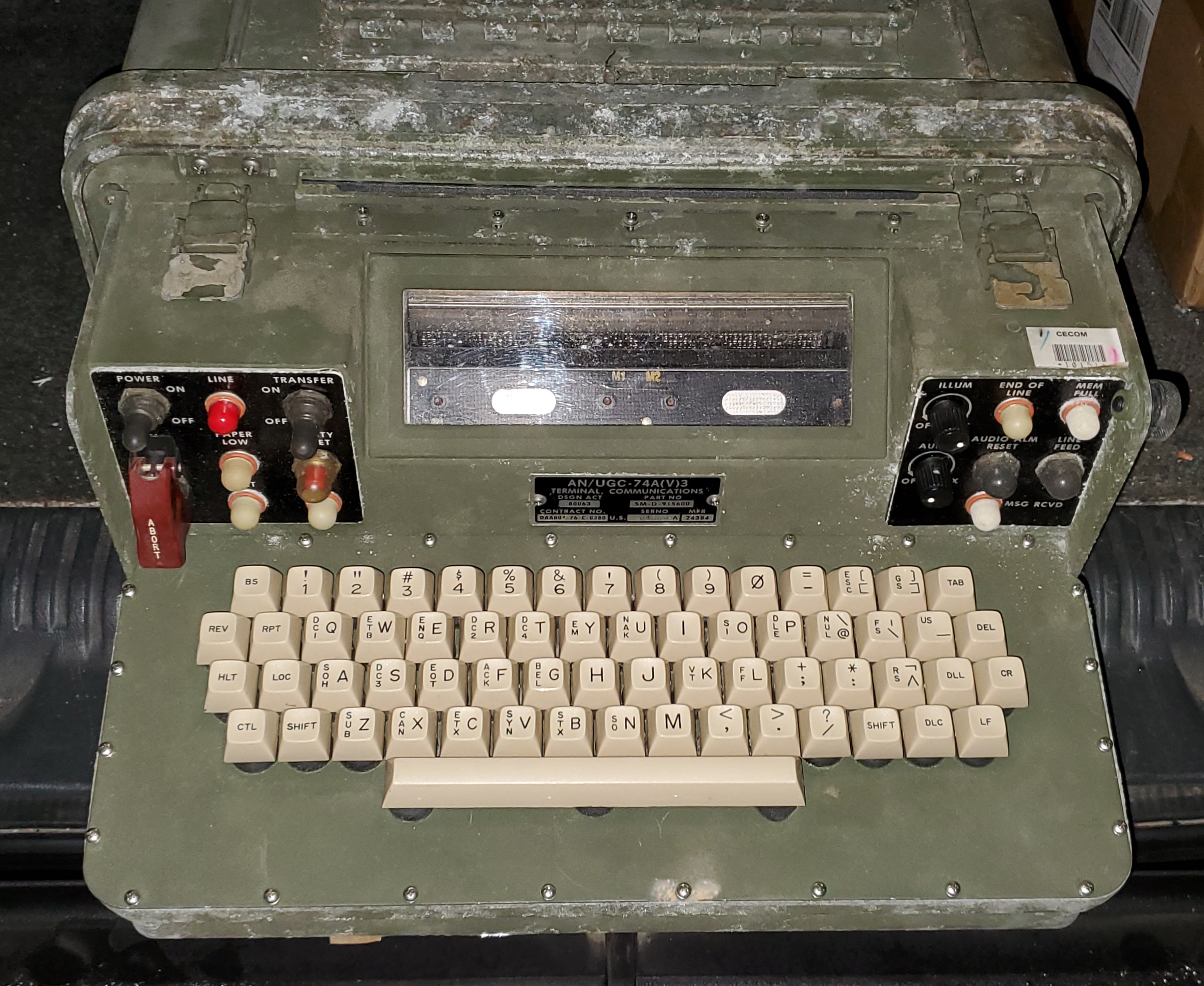
The primary device used to compose and receive these messages was the AN/UGC-74 Communications Terminal. It was considered an intelligent terminal device, capable of composing messages offline and sending them on demand. It also had a 16K receive buffer to store incoming messages in the background to be brought up and printed as needed. In the mid-80s, the only other “intelligent” device I used was my Commodore 64 computer. Even though the Commodore 64 had more computing power, the AN/UGC-74 was a remarkable curiosity. I only ever used the device for a year before I was trained on the use of more modern satellite text communications terminals.
Fast forward to the 21st century, I’ve long since developed a keen interest in owning an AN/UGC-74 for my own. There’s not much I could do with it, but they were available as surplus equipment, and I found out that they can be used for RTTY communications in HAM Radio… kitschy, but cool. The problem was, I could never find one, or at least an affordable one, before someone else bought it ahead of me.
Fast forward to the year 2022. I finally have TWO of them. Got them for a great price, and between the two of them, I hope to get one fully operational.
Details about the AN/UGC-74

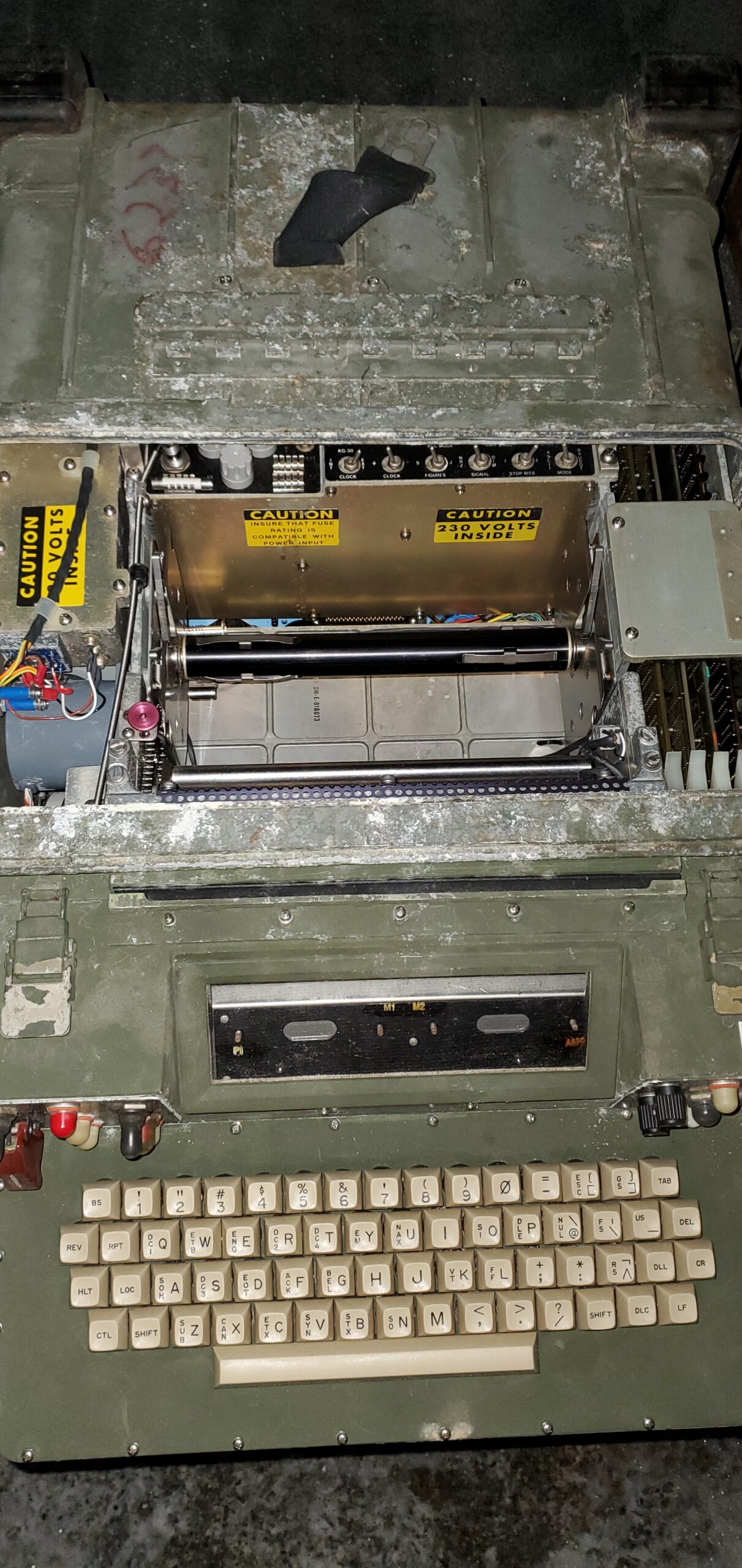
Keyboard of the AN/UGC-74 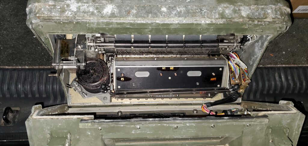
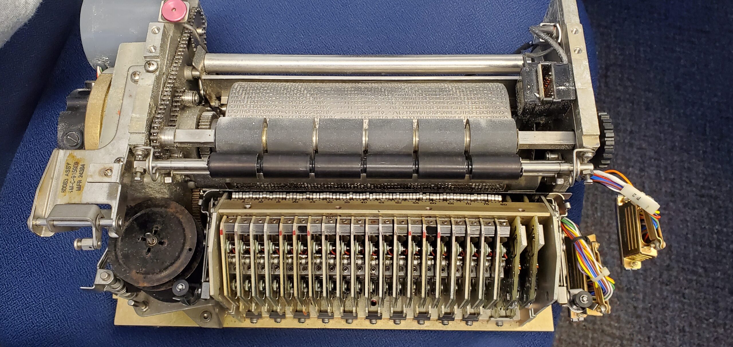
Print mechanism of the AN/UGC-74 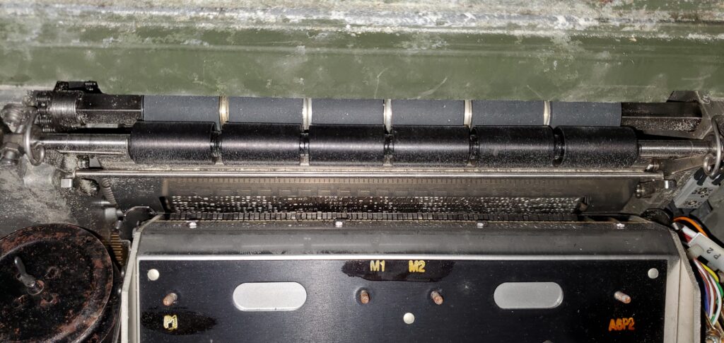
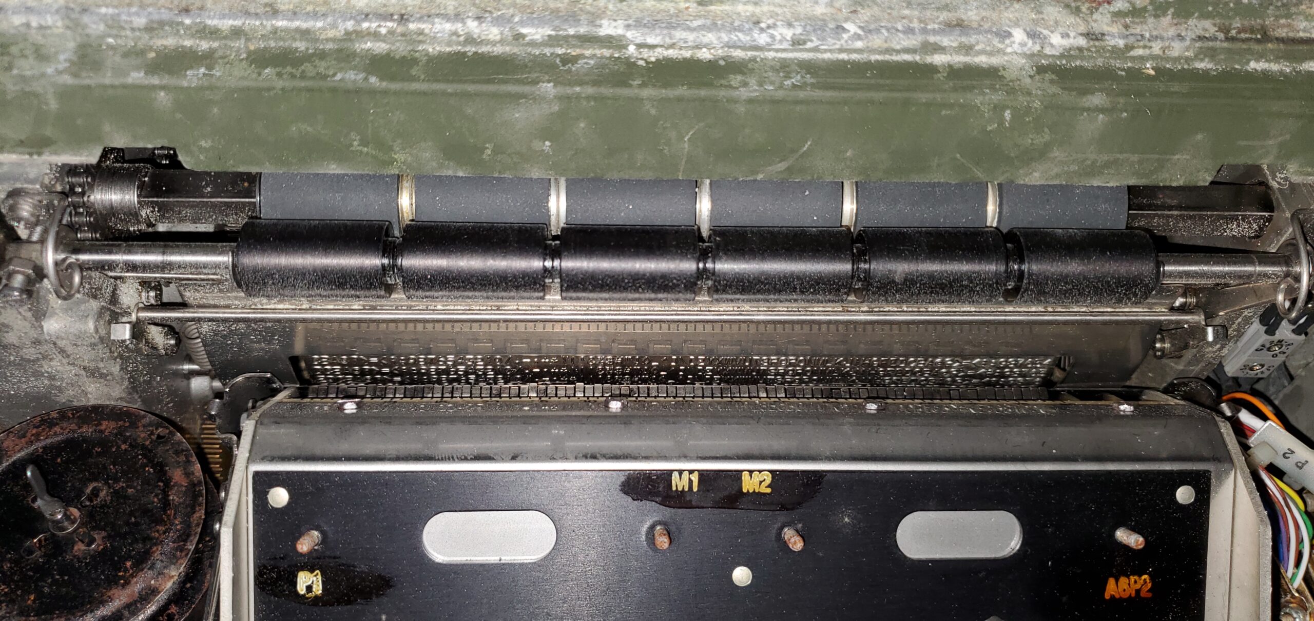
Print drum of the AN/UGC-74 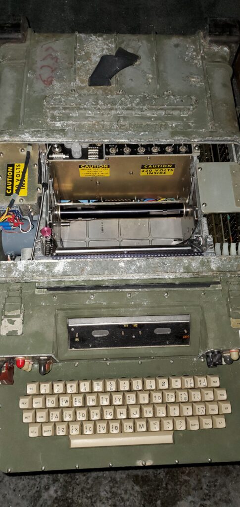
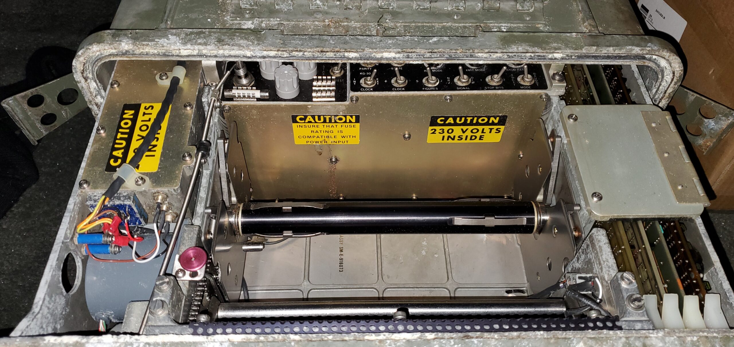
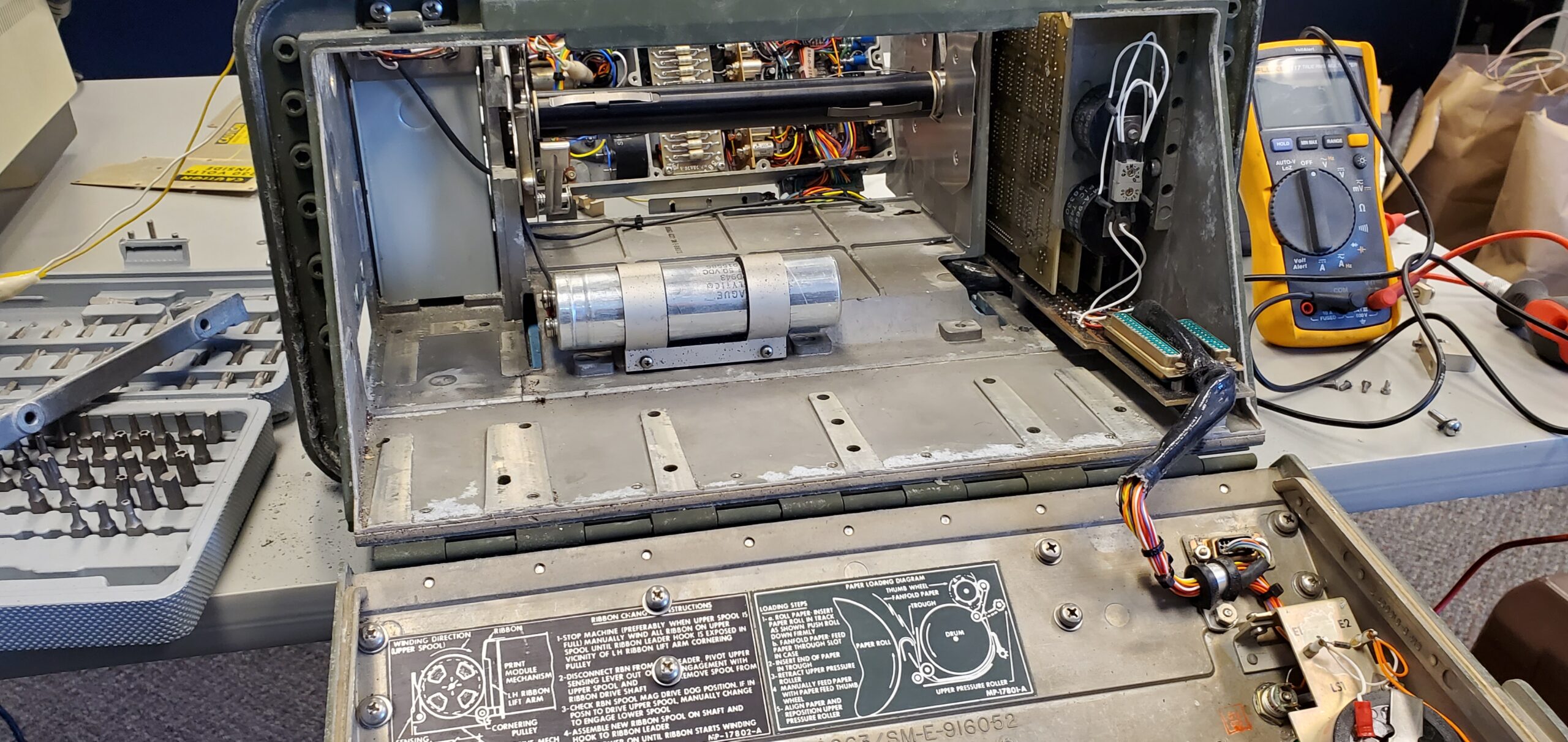
Paper compartment of the AN/UGC-74 
Close-up of the paper compartment of the AN/UGC-74 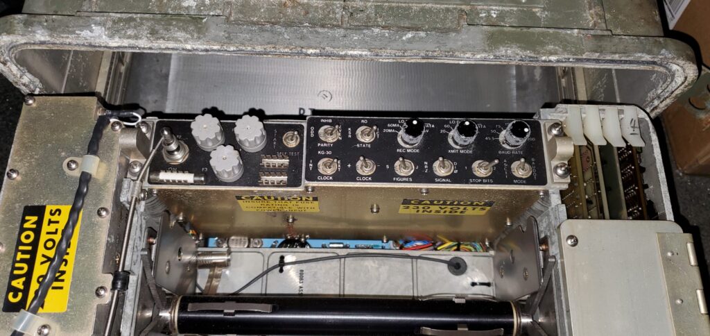
Configuration switches of the AN/UGC-74


Specifications
- Weight: 100lbs.
- Dimensions: 17.5″W x 21.75L +x 9.5″H
- Output type: Paper roll, 80 column text
- Print mechanism: Character drum w/ hammers, 60 characters per second
- Operating voltages
- DC 26v (+/- 4v)
- AC 120v (50, 60, or 400Hz)
- AC 230v (50, 60, or 400Hz)
- Data signals
- 20ma, 48v
- 20ma, 130v loop
- 60ma, 130v loop
- LO Data, inverted or non-inverted, RS-232 compatible
- Keyboard: 62 key, ASCII and BAUDOT compatible
Triage
With two AN/UGC-74 units in my possession, along with a weekend getaway at a vintage computer repair workshop, I started to disassemble them to find out what makes them tick, and what works or not.
The first thing I had to decide is if I wanted to test functionality with a measure of delicate prudence, or go all in and just fire it up. I decided to do the latter. However, you can’t just grab a cord and plug it in… unless you have an official Assembly, Cable, Power, 115 Vac, SM-D-764481 that’s designed to hook up the AN/UGC-74 to a 115v mains line. I did not have one of these, so I had to rig an alternative.
The power input for an AN/UGC-74 is a multi-pin industrial bayonet socket with 12 pins sharing two different diameters. The same socket is to be used in conjunction with a plug that has a number of pins shorted to each other to “wire up” the power supply in an appropriate way to accept any particular power input. The image below shows what I had to wire together.
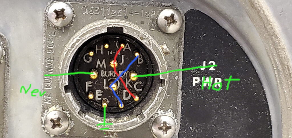
I had to short pins A, J, and C together, then pins B, L, and D together, then feed the Hot side of the 115v mains into pin K, the Neutral side into pin M, and connect mains ground to pin E. What made it difficult is that I didn’t have an associated plug to do that easily, so I opened up the power distribution module that houses J2 and used various jumper wires to effectively connect all the appropriate pins and power sources. The inside of the power distribution module looks like this:
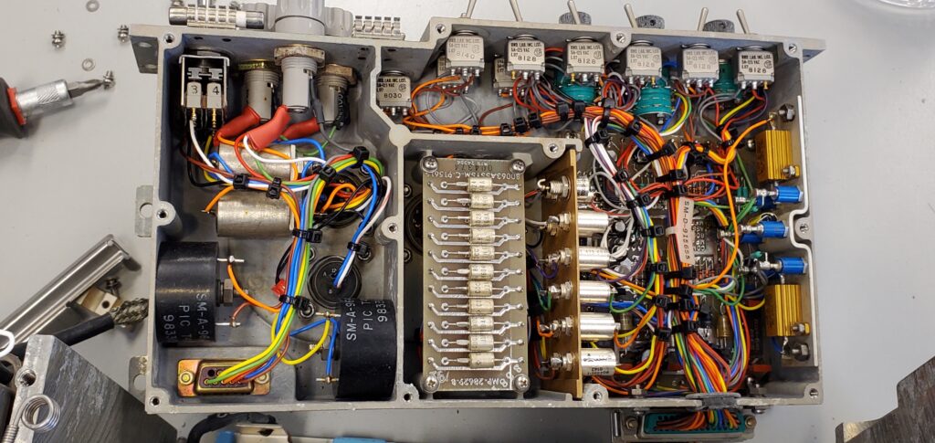
The left side has all the power distribution and socket J2. All the wires on the inside are terminated with heat shrink tubing to protect them. It was difficult finding points to connect jumpers. I ended up having to connect to the pins on J2 in combination with following the wires going through the DB9 connector you see in the lower left, which go to another module housing I had to open that had better looking connections to tap.
After finishing the rats nest wiring rig, I powered on the unit. I got lights, but no action. The unit is supposed to initialize the print mechanism, and start the print drum spinning. I just had lights. I double-checked the wiring to see if I missed a connection or two, but it all looked good. My guess is the CPU was unable to start initialization. By this point in time, I was ready for beer, coffee, a hearty lunch, so I can prepare to spend some extra time doing some deep troubleshooting.
Digging in
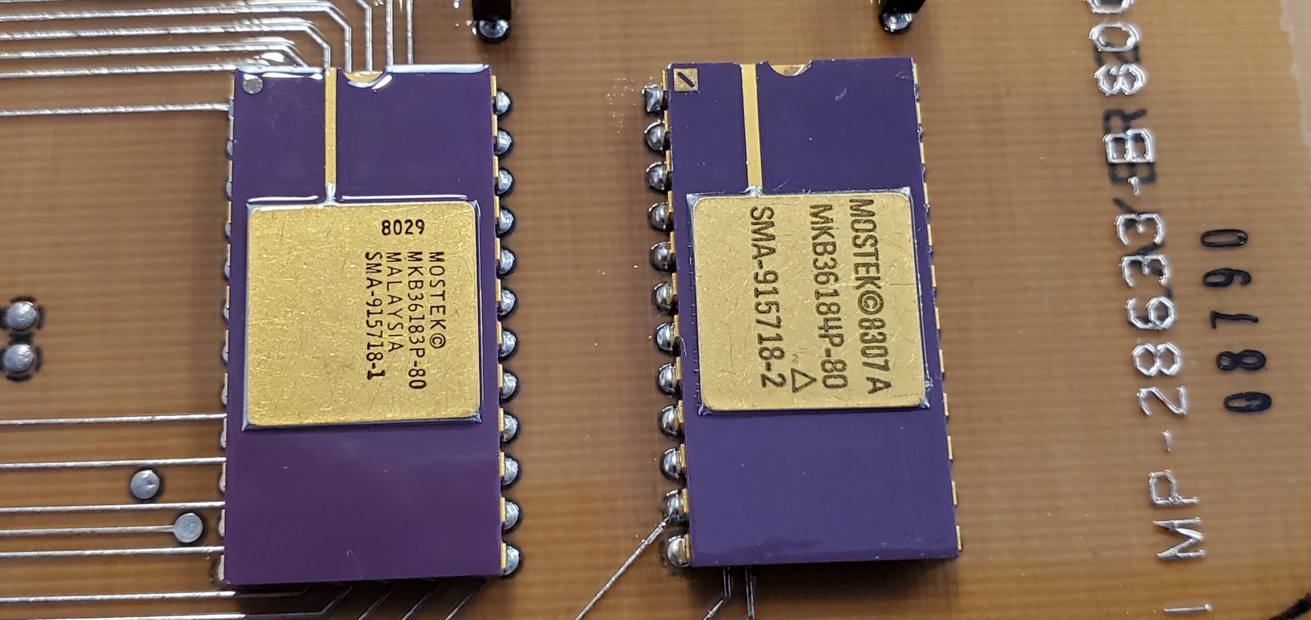
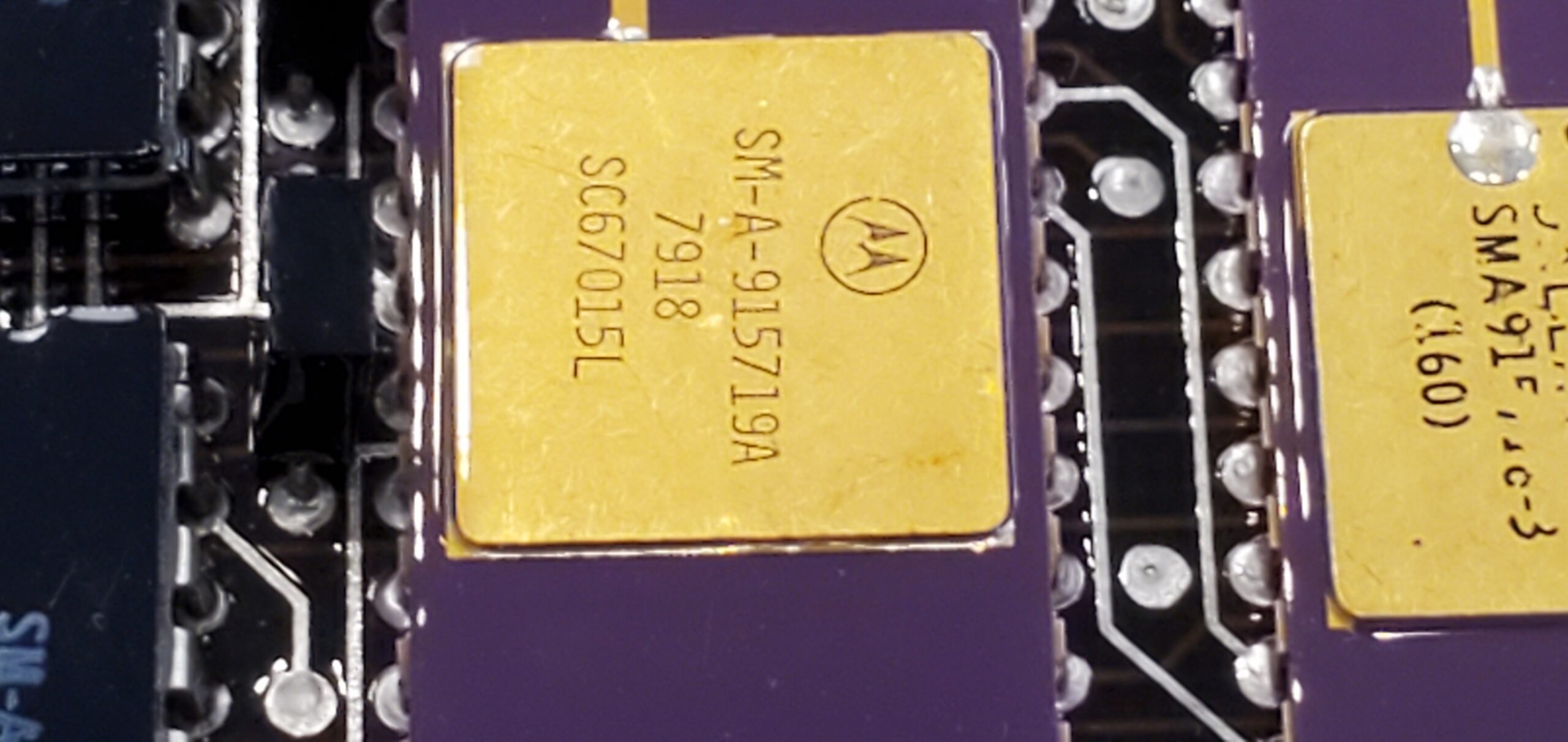
The next thing I did was pull the four main boards out. I was curious to see what parts are on them, and to provide insight on my Twitter feed for those who were also just as curious. The four boards are a CPU, Memory, Communications, and Print Driver boards. Each one of them had a weatherproof coating on them, and are each uniquely socketed to prevent mixing them up on the main signal bus.
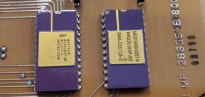
ROMs of the AN/UGC-74 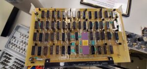
Printer control board of the AN/UGC-74 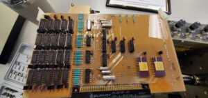
Memory board of the AN/UGC-74 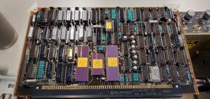
CPU board of the AN/UGC-74 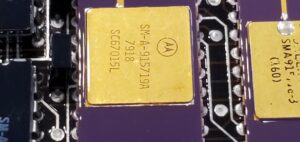
CPU of the AN/UGC-74 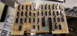
Communications board of the AN/UGC-74


Now it was time to go down the rabbit hole. I had to start removing screws, and there were a LOT of screws holding assemblies in place. But first, I wanted to learn more about the print hammer assemblies. I started removing the ribbon guide, then the lockdown bar holding the hammer assemblies in place. You can see how the entire ribbon guide covers the hammers. Once that is removed, then there is a brass bar that mounts into notches along the back edge of the hammer assemblies which needed to be removed. Then finally, you can pull each hammer assembly out individually. You can see what they look like in the pictures. There are four hammers stacked beside each other, and are individually activated by tiny solenoids.
Printer ribbon guide and shield 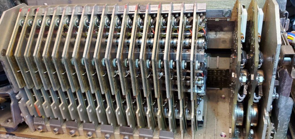
Print hammer modules installed in their slots 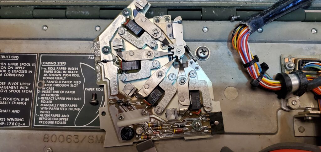
Side view of a print hammer module


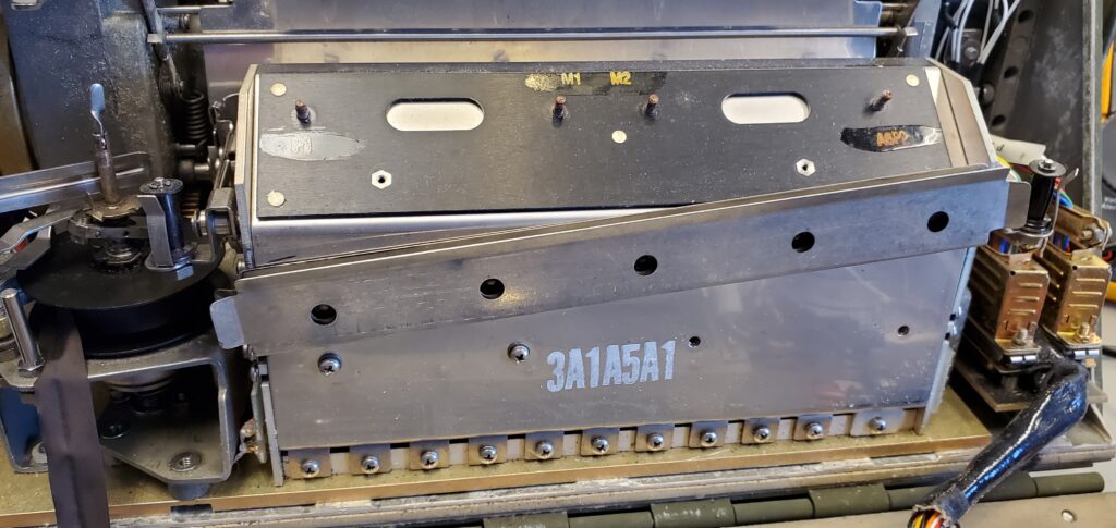
After playing around with the hammer assemblies, I looked deeper into the print mechanism to find out why it wasn’t spinning. After a cursory look into dark cavities of the mechanism, I noticed something amiss. There was a gear that was tumbling loose on the left side of the print drum. Unfortunately, it was buried deep in side the mechanism and I didn’t have anything that would be able to pull it out. So I decided to tackle the task of removing the entire printer mechanism.
One thing to note about this kind of military gear is that it’s extremely over-engineered. By the sheer count of clips and screws that hold things in, it was built to withstand all kinds of movement, impacts, and jostling. This is why the printer mechanism itself, which only takes up about one-quarter of the AN/UGC-74’s overall volume of space, is held in place by 15 screws!
After removing the print mechanism, the loose gear was able to fall out. Upon closer inspection, it looks like the bolt that mounts it in place has simply sheared in two. So now, I felt this mechanism might be more difficult to fix, so I proceeded to work on my other AN/UGC-74.
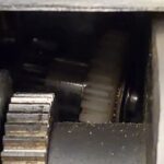
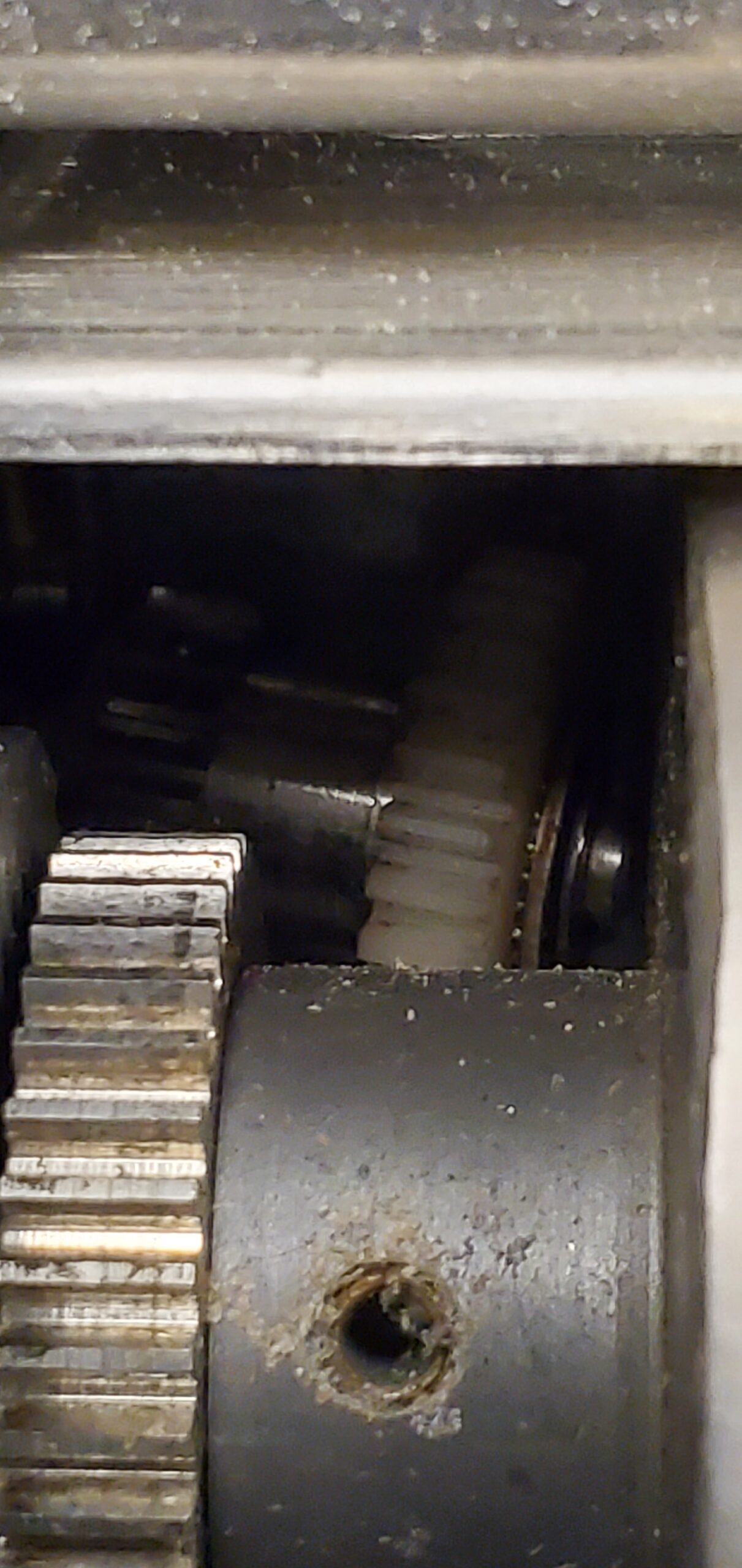
Loose gear 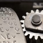
Close-up of loose gear 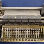
Print mechanism completely pulled from AN/UGC-74 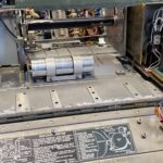
Cavity of AN/UGC-74 with printer mechanism removed

The Second AN/UGC-74
Now that I have a little more familiarity with the AN/UGC-74, I had less anxiety over working on the other unit. It didn’t take me long to hook up the other unit with power and fire it up. Believe it or not, the drum started spinning on it like it was supposed to. However, it did so as soon as power was applied, regardless of the position of the actual power switch.
At least those around me got to witness a level of its operation. They heard and saw the drum spinning like it should. However, it was a bit squeaky when it was doing so, and there was no print mechanism initialization. The unit should have attempted to print a power-on text. I couldn’t remember if the lack of a paper roll would prevent the printing action or not.
Deja Vu all over again
This time, I basically repeated the steps I took with the first unit. I proceeded to remove the ribbon guide, then start to remove and check the print hammer assemblies.
In this unit, I found that three of the hammer mechanisms were missing the tips of their hammer heads. That rendered the mechanisms useless because the stacked hammers were riveted in place, so there is little chance of repairing them to the part level because it would be difficult to remove and replace those rivets.
I took a peek at the area in the print mechanism where I found the loose gear on the first one and saw where it was supposed to be. The gear was intact and in place on this unit. It’s actually in a spot which allows it to drive the printer ribbon feed. I guess I could have stopped there, but nearly all the paper feed pinch rollers were dried up and had crumbled off. Even if this print mechanism spins as it should, it would be troublesome for it to feed the paper roll through. So, I proceeded to remove the print mechanism.
After yet another 15 screws, I had the entire print mechanism out of the case. Once it was removed, I started following the official US Army Technical Service Manual instructions for disassembling the print mechanism. The step by step instructions it provided was easy to follow…
Remove printer assembly as directed in paragraph 5-11K.
Remove ribbon mechanism as directed in paragraph 5-11L.
Remove printer subassembly as directed in paragraph 5-11M.
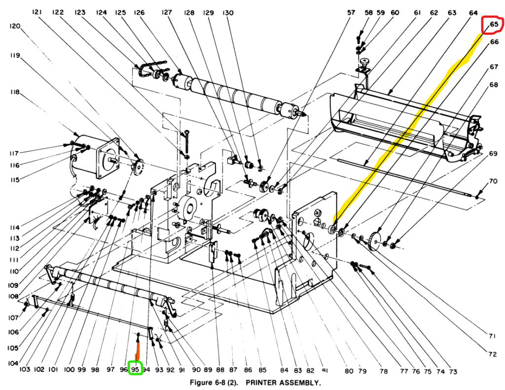
Loosen and remove two screws (13) which secure right vertical wall (right-hand plate).
Loosen and remove four screws (73) securing paper trough (63) to right vertical wall.
Loosen and remove screw (56) which secures timing mechanism and remove timing
mechanism (52, 53) by disconnecting A4J1 and A5J1 (50).
Lower upper pressure roller (91) and remove spring (90) on right hand end of upper pressure
roller shaft.
Remove retaining ring (89) securing upper pressure roller to right vertical wall.
Remove retaining ring (70) and slide shaft (64) through right vertical wall.
Remove retaining ring (65) from lever assembly (93).
Gently remove right vertical wall, being careful to secure spring (92).
Remove paper-out switch bracket (5) from right vertical wall.However, I started to find a problem with the parts identification. For example, “retaining ring (65)” is not a ring in the exploded view. Part number 65 refers to a bearing that is not related to “lever assembly (93).” The retaining ring is actually part number 95. See highlights below:
I’ve learned from the past that when you find one mistake in an “official” manual, there will be other mistakes. So since I was on a limited time budget where I was working on these units, I decided it was time to pack up what was done so far and turn it into a long term project at home. I’d want to review all part references and diagrams and correct the mistakes before I continue its refurbishing.
That about sums up my progress so far. But if you’re curious, here are additional pictures I took during the repair session, which also shows the printer mechanism partially dismantled.
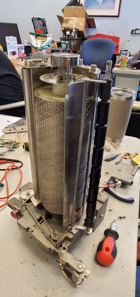
Printer mechanism with its right side removed 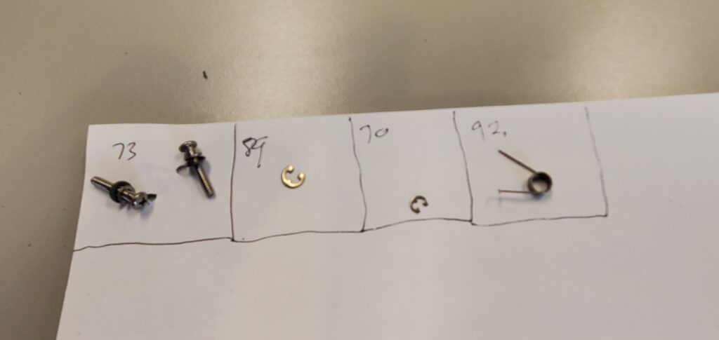
My makeshift parts tracking system
Check my Shapeways account again. I made available another one of the gears used in the Magnavox D8443. I designed this gear using the same techniques as the first gear, but I have not tested it. That is because my D8443 still has a working gear of that kind and to try to replace it now would require destroying the original gear first. I’d rather not break something that’s working at the moment. I have the gear posted at a low price right now due to the risk being taken by those who wish to try it for themselves.