I was attending a repair workshop this weekend along with other vintage computer aficionados. These (paid) workshops are typically to provide working space for those who need an area to work on their vintage computer systems, or even to pick the brains of other attendees of the workshop.
On this visit, I brought a portion of my TRS-80 Model I collection to figure out what works and what doesn’t. I had four Model I computers. Three were in my collection for a while. One was a unit I got at the recent VCF East or Festivus event (I forgot which…). I also brought two expansion boxes and an official TRS-80 monitor. One Model I had Level I BASIC and did NOT have any kind of keyboard de-bouncing modifications done to it. That meant that my Hello World test program looked like this:
100 PRRIINT  "HEEELLLO";;
20 GOTTO 10
Too many keys were repeating automatically. A known issue with earlier versions of the Model I. There is a software fix, I believe, for the issue, but I wasn’t ready to pursue it. So that one I set aside for another day.
Another Model I had a strange raster display that looked like a detuned TV signal. I eventually determined that the 5V source was “pulsing.” It would go from 0V to 5V, then drift down to 4V over two seconds, then drop to 0V, repeating again after a few seconds.
…I didn’t have the patience for that one, so I set it aside for another day, too.
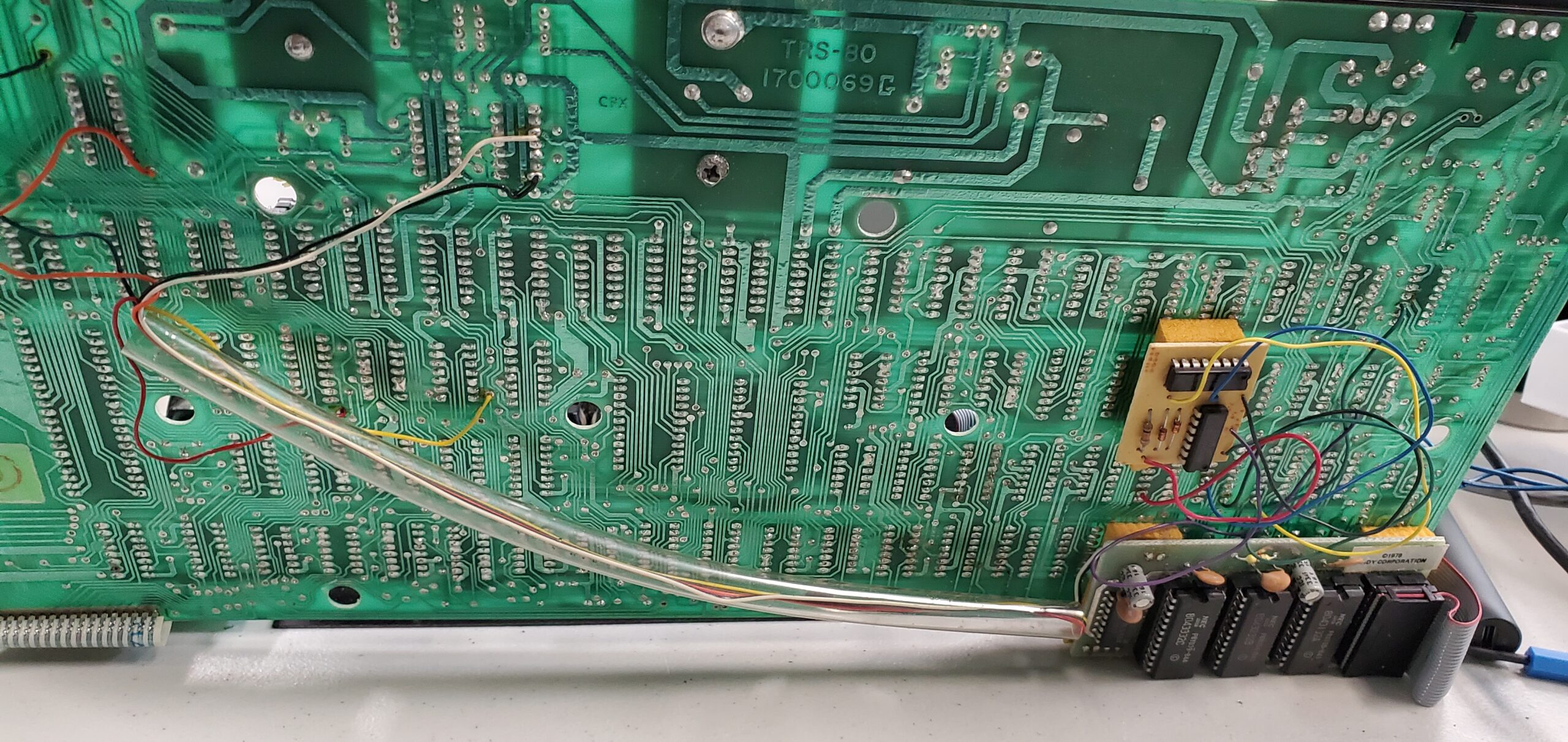
A third Model I booted right up to Level II BASIC and typed just fine. At least one of my TRS-80s was working :). So I hooked up one of the two expansion interfaces I brought…. NOTHING. The Model I would still power up fine, but I could not see the extra memory from the E/I. So… I hooked up the other E/I.
Still no change… So I opened up the second E/I to troubleshoot.
After poking around for an actual service manual online, I found a troubleshooting guide. I had trouble getting 5V in the E/I. All the parts looked good. Nothing was blown. Just wasn’t getting 5V. So after closer examination of one of the

LM/UA723 voltage regulator chips, I discovered that a pin was broken off the chip. I pushed in the remains of the pin into its socket and heard the click of the E/I’s system relay. Well, since I did not have a replacement LM723 regulator, I just rigged in a fix for the pin and now the E/I was working. When I plugged it back in with that Model I, I saw the extra 32K added to the system.
YAY!!! Now I can test out the external floppy drive I brought with me. But wait… I brought the wrong floppy drive data cable… (GRRRRRR….)

So… I decided to work on the fourth Model I computer I brought with me.
I powered it up and it looked good, except for an odd pattern of dots on the display. Everything seemed to work fine on it as a Level II BASIC system that properly connects to the working E/I, but I couldn’t get rid of the dots on the display. The dots didn’t seem to affect computer operations. They just took over their character spot on the display where other characters were expected to be. I wrote this test program to check and see what happens as I fill in video RAM with data:
10 PRINT "X";:GOTO 10
I get a screen full of “X” characters except for where the dots are. I assumed there was something wrong with one or more of the 2104 Video RAM chips, but the locations of the dots would indicate the problem exists on several chips. I will have to read the technical details to try and match actual circuit operation with the pattern of failure seen on the screen. There could also be a timing or glitch issue in the video chain circuitry. I did not have time to research all of that, so I set that unit aside for a future date.

I mainly brought these systems to the Workshop to do triage of their unknown condition. At least I had one full working Model I w/ E/I, albeit without knowledge of a working floppy drive at the moment.