Update (again) – 30 APR 2020: I’m, again, back at it. Something mysteriously fell through with the operation of the RC2019/10 Retrochallenge. The entire contest just went stale with no oversight. So… now that someone else took over the management of the Retrochallenge franchise, I thought maybe I’d give it another go.
I decided to continue with my MOBIDIC project…
Update – 12 SEP 2019: I’m back at it, again, to continue with another Retrochallenge. But, instead of picking something new to not eventually finish, I’ll rehash an old one which means a great deal to me. The only thing is, I will use the incentive of Retrochallenge to focus more of my limited free time to do so. So, instead of creating an entirely new post for this, I’ll just rehash last year’s post as a starting point.
Aaaand…. another Retrochallenge! I still try to participate in these whenever I get wind of them, even though I rarely ever finish one. I do it for the fun and camaraderie. For those who have started to put bets on me even starting on one or completing one of these fully, here’s a hint… I WON’T (technically) FINISH THIS ONE!
What the heck does that mean?!?
It means that I have a Retrochallenge idea I plan to pursue, but it’ll take a lot longer than one month to actually finish the project I plan to work on during the challenge. Some of you might have known, or have seen, that I had an introductory demonstration of an emulator for a VERY vintage (or ancient) computer called the MOBIDIC… a.k.a. MOBIle DIgital Computer at the Vintage Computer Festival East XIII.
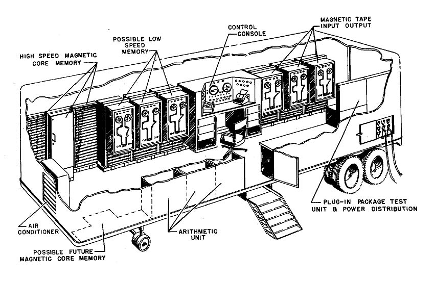
The MOBIDIC was a portable (by 1960’s standards) Von Neumann style computer system designed by the U.S. Army and built by Sylvania. The beast of a machine was all transistorized and mounted in a tractor trailer, ready to be hauled on-site wherever computing and data processing resources were needed. My exhibit demonstrated and introduced the MOBIDIC to the public as a vintage computer worth learning about. An attempt is being made to recreate a full sized MOBIDIC computer using emulation as its core. THAT is my Retrochallenge for this session. I have already emulated an idling CPU for the project before the VCF East demonstration. I have also somewhat created a replica output, which was also displayed at VCF East. The MOBIDIC’s standard output is rows of blinkenlights, but it can also interface with punch or magnetic tape, and teletype output. In the available time allotted for the Retrochallenge, I plan on making the CPU portion do more than idle (running only housekeeping tasks) into a CPU that can interpret the MOBIDIC op-code set and actually process a program. Will this be an easy task or not? I don’t know, nor do I care if it is easy. I WANT to do it, and the Retrochallenge is incentive enough to keep me motivated to continue the work I have started earlier this year.
I’d wager that the MOBIDIC is the one of the oldest computing platforms ever addressed for any Retrochallenge. It was designed and built between 1959 and 1962. And since it was comprised of so many transistors, it’s more cost effective to emulate one rather than replicate one.
Update – 1 OCT 2019: Retrochallenge RC2019/10 is now underway!!!
This update will summarize what I have done so far. I have already decided on the system I will use to recreate the MOBIDIC. Keep in mind that the MOBIDIC was all transistorized, and did not have any form of integrated circuit. Recreating a MOBIDIC in its true form will be very time consuming and costly. Emulation (or simulation) is really the only sensible way to recreate it.
I decided to use the ESP32 platform for emulation. I like that it not only has a very large non-volatile RAM capacity, but as the complexity of emulation begins to occur, it has a large amount of program space for the compiled application. The ESP32 runs on an Arduino platform. It is this platform which will be used to create the source code for emulating the MOBIDIC. The built-in WiFI and Bluetooth capabilities could be leveraged for remote control in the emulation of original MOBIDIC peripherals.
The MOBIDIC in its base form used switches and lights to allow for input and to display bus and memory status, not unlike the MITS Altair. Since it’s cost prohibitive at the moment to buy, mount, and wire up the large number of lights and switches needed to create a minimal panel, I have opted to emulate the light output using ANSI control codes to a serial terminal which supports ANSI block graphics.
The lights I need to emulate, at a minimum, are the lights that represent the SYSTEM BUS, the ACCUMULATOR register, contents of an OPCODE instruction word, the PROGRAM COUNTER, and the system’s TIMING FUNCTION. Here is a sketch some of the indicators in their natural layout.
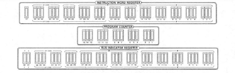
With the ESP32 being Arduino based, I can use any one of the Arduino serial libraries that are capable of generating ANSI codes. As of now, the emulator just generates random RAM content, then rolls through RAM to display each byte on the system bus, continually outputting the status lights into my Windows 10 based terminal program. Right now, this is what the emulated output looks likes.

The monitored registers are named in green, bit position is in white, bit segments in cyan, and actual bits are in yellow, represented by a single dot as off (or zero), and a square as on (or one).
Notice anything unusual about the registers…? How about that funky architecture, huh? What is that… 37-bits?
It certainly is! Well, technically, it’s 38-bit. the extra bit was utilized as a RAM parity bit by the MOBIDIC to allow the system to halt on a parity error. Parity bits are not needed by today’s standards because the concept of RAM in emulated program structures is a moot point, so therefore, I have opted not to fully emulate the parity bit.
The MOBIDIC was designed before even the architecture for early integrated microprocessor was designed that started the current industry on the 4, 8, 16, 32, etc. bit wide control architecture was readily accepted. Engineers of the MOBIDIC were sort of working from a clean slate in the concept of a Von Neumann computing system. Unlike today’s CPU architecture which relies on opcodes being retrieved from RAM in one byte, then the operands retrieved from the next byte, MOBIDIC engineers decided to make the RAM bit size big enough to contain a bit representation of an opcode, along with any address and operands needed by the opcode, in a single byte of memory.
For example, an opcode byte in RAM contains the following segmented data:
| Bits (from right to left) | Purpose |
|---|---|
| 12 to 1 | Alpha portion of the opcode, which contains the RAM address the opcode is to reference in its operation |
| 15 to 13 | If set, references one of seven specially designated registers, such as the accumulator |
| 27 to 16 | Beta portion of the opcode. Could represent a number that gets added to a designated index registers referenced in the next bits, or be used to indicate another RAM address, depending on the opcode |
| 30 to 28 | Gamma portion of the opcode, which indicates which index register, if any, that is to be used during opcode processing. In effect, the contents of the indicated index register is added to the address value in the Alpha portion to generate a new RAM address for the opcode to reference. |
| 36 to 31 | Bit representation of one of 64 opcodes. |
| 37 | Spare bit. Used by some operations, either explicitly by the program, or by specific opcodes. |
Right now, my emulated MOBIDIC is dumb. While it can manage the cycling through RAM, it cannot compute. My next step in the Retrochallenge is to integrate opcode processing by the emulator, so it can do some form of work.
Update – 22 OCT 2019: Crossroads…
For the better part of October, I have been trying to figure out which path to take for the MOBIDIC. Should I continue to perfect the output and work to “hardcode” the software, just to see it process programs I design, or should I give it some interactivity, THEN use that to develop software for it?
Since the operator details of the MOBIDIC are lost in the annals of time, I have a great amount of leeway. I can basically recreate the wheel if I want to, even though it grinds unmercifully against my nature of purity in emulation. However, without anyone known (alive) to guide me with real experience, there is little I can do to achieve purity. So… that leaves me with a lot of options. Because of this, I opted to create a rudimentary operating system for the MOBIDIC, called Mobidic Operating System, or MOS.
With a direction decided, I continued with the Retrochallenge with vigor…!
Since I’m using the ESP32 platform, I felt it appropriate to work with the serial port interface, which already produces the output, to now handle input in the form of a command line. But first, I made a slight change in the output.
My current iteration of the emulator is limited to 500 bytes of 38-bit memory. In order to show a nice “blinkenlights” demonstration, I originally loaded random values into all 500 bytes of memory. When the emulator ran, it simply looped through all 500 bytes and showed their values on the BUS set of lights. This was not a completely proper display. Since all memory transfer actions do appear on the BUS before being sent to other registers, any memory read would impress its bits on the BUS. However, there’s a strong possibility that the bits would appear on the INSTRUCTION WORD set of lights. Therefore, for demonstration purposes at the moment, I moved the BUS output to the INSTRUCTION WORD output.
Next task… create a useable command line interface. I had some issues with this. I work best when I can visualize the desired activity. Right now, I have a serial terminal displaying every blinkenlight I can send to it, as fast as I can sent to it. Now, I need to process input from the terminal program. I find it difficult to manage two-way asynchronous data on a synchronous medium. But, once I stepped back a bit and realize the Arduino Serial object will do a lot of the work for me, the understanding became more clear.
I was always afraid that managing two-way data through a serial connection would result in a lot of lag an delay. My worries were unfounded when I discovered that 115200 baud is REALLY FAST compared to the speed of human interaction. I created a function that checks input from the terminal program and processes it accordingly.
Right now, I simply split an 80×50 terminal screen. The upper half displays the continuous ANSI output that creates the blinkenlights. I reserved the bottom half for terminal interaction, something that the original MOBIDIC didn’t have in this capacity. I’m treating the lower half as a CRT, as opposed to a teletype which was readily available for the MOBIDIC. The terminal program leaves me with little space to work with, so I had to compromise between a permanent teletype output on continuous paper with something I can clear away programmatically due to limited screen space.
As of this update, all I have been able to accomplish is basic input on a single entry line located at the bottom of the terminal screen. I envisioned a ZX-81 style of input where the next line typed by the operator is at the bottom of the screen and will either be immediately acted upon, or be inserted above when the ENTER key is pressed. Right now, I only have it taking my typed input, captured as a CHAR array, and displayed on the bottom line. It took some time to get just that working as expected.

Thus, we now have MOS! The Mobidic Operating System. Hey… it’s a start! : )
Update – 28 OCT 2019: MOS 0.2 alpha release candidate 2… (and other incremental post-nomials)
The Month of Retrochallenge™ is drawing to a close. As I mentioned at the beginning of my challenge, I did not expect to finish this project. However, I consider this Retrochallenge a personal victory because I did fulfill my promise to actually work on it throughout the month of October, something I wasn’t able to do in the past.
I still did not get the MOBIDIC system to actually process code. The epiphany realized earlier this month is that I would find coding applications for it very tedious if I did not implement a means to enter program code directly. That is why I decided to implement a rudimentary operating system (called MOBIDIC Operating System), something the original bare metal machine fundamentally lacks (or has otherwise been lost in the annals of time). So I continued my enhancements to the MOS interface from earlier in the month. So far, I can do the following:
- CLS – Clear the command screen
- RUN – Start running the program
- STOP – Stop running the program
That doesn’t seem like much, but they are very important commands. You know from the previous update that I can type in a line (of anything), hit ENTER, and the line queues up on the command screen. Well, eventually, that will fill up. So I implemented the CLS command to clear that screen and reset the line pointer to the top again.
Then, I realized that it was in MOBIDIC’s original nature, unless told to do so, would not be actively running any programs. On the real system, that’s done with a mechanical switch. I have not implemented an electrical control panel for this, yet. So I simply implemented the RUN command to start the system working through the program counter and Timing Functions. Inversely, I implemented STOP to bring it to a halt. This doesn’t seem like a lot of work, but I had to rewrite the method I used to manage the Timing Functions to make it work as envisioned by the physical MOBIDIC machine itself.
While modern computers generally advance through program code by reading and processing opcodes in a few CPU cycles, the MOBIDIC moves a little differently. Timing Functions are the most regular form of sequencing used in the system in beat with the system clock. In essence, one Timing Function loop (of seven steps) will advance a single opcode processing, along with the Program Counter, then the subsequent pre-loading of the next opcode to be processed in the Timing Function loop.
I used a Finite State Machine (FSM) to initially manage the Timing Functions. In order to be true as possible to MOBIDIC cycle timings, I needed to be able to cease system activity when stopping a program. With the FSM, some automated state changes could have interfered with continued code execution if started/stopped at random. So I implemented Timing Functions into something a little more archaic that allowed me to control code execution with something as simple as a flag being set indicating the system is in a RUN state or not. But then again, the MOBIDIC was archaic by nature, even though it was a technological marvel of its time. Using a FSM was probably a little too overachieving for my needs in the first place.
Now that I have RUN and STOP implemented, that means that by simply connecting to the system via TTY, it doesn’t start to flash blinkenlights right away. I must issue the RUN command first. Then again, the real MOBIDIC didn’t just start running calculations as soon as its generator truck got powered on either. 🙂
I still have more to do with this project. MUCH more. But with the accomplishments I made in this month of Retrochallenge, I certainly developed more momentum to continue with it!